


Ruian Chuangbo Machinery Co., Ltd. is specialized in manufacturing of machinery parts.
Thin-walled workpieces show up everywhere in manufacturing — tubes, rings, sleeves, housings, lightweight structural pieces, you name it. They can look deceptively simple from a shape standpoint, but machining them well means paying real attention to how the part gets held. A thin wall responds to clamping pressure, cutting forces, and shifts in support in ways that can quietly change its shape during production.
Workholding, then, ties directly into how the machining actually turns out. A chuck isn't just there to keep the workpiece from moving. Its contact area, where it clamps, how support gets arranged, and how much pressure it applies all shape the component's behavior before, during, and after the cut. A setup worth using aims to give enough stability for machining without pushing the part into unnecessary deformation.
Why Are Thin-Walled Workpieces So Tricky to Clamp?
Thin-walled parts don't behave anything like solid ones, mostly because their walls just don't have the same structural backbone. Apply clamping pressure, and the workpiece can flex, drift slightly oval, or deform locally in ways that aren't always obvious. Sometimes the problem stays hidden while the part's still clamped and only shows up once it's released.
Geometry plays into this too. Large diameters, narrow wall sections, uneven shapes, long unsupported stretches — all of these demand extra thought during setup. Machining adds yet another variable on top, since cutting forces shift as material comes off the part.
Wall thickness, workpiece diameter, how the material behaves, contact area, clamping location, and machining direction all deserve consideration together rather than in isolation. Clamping isn't really a step that stands apart from the rest — it's woven into the whole machining process.
How Do Mechanical Chucks Deal With Clamping Pressure?
Mechanical Chucks hold a workpiece by creating contact between the chuck body and the part itself. With thin-walled components, how that contact spreads out matters a great deal, since pressure concentrated in one spot can trigger local distortion pretty easily.
A workable setup considers where the workpiece actually gets held and how much surface is available to support it. Contact that's wider and more evenly balanced tends to spread the applied force better, while uneven contact leaves the part reacting differently depending on where you look around its circumference.
Clamping condition shapes the machining process in more than one way. Too much pressure can temporarily distort the workpiece shape, while too little support risks movement the second cutting begins. So the goal isn't just cranking up holding force — it's building a stable relationship between the workpiece, the chuck, and whatever cutting operation follows.
Does Internal Support Actually Help With Thin-Walled Machining?
Some thin-walled components respond better to internal support, especially ones with a central opening. An Expanding Mandrel Chuck holds the workpiece from the inside, pushing outward against the internal surface. That flips the direction the holding force comes from and can offer useful support without leaning entirely on external grip.
Internal support tends to make sense when the outer surface needs machining, or when external pressure risks messing with the shape you're going for. It can also serve as a solid reference point for tubular parts, rings, and sleeve-like components.
Still, choosing this method comes down to geometry and the machining sequence involved. Internal support isn't automatically the right call for every hollow workpiece out there. Internal diameter, wall condition, available contact area, and how much machining access is actually needed all deserve a look before settling on a setup.
How Does Support Position Affect Workpiece Stability?
Where support sits has a pretty direct bearing on how a thin-walled part behaves once cutting starts. Concentrate support in one narrow area, and other sections stay flexible, reacting to cutting forces in their own unpredictable way. A better-arranged setup helps the part hold its intended position all the way through.
Different workpieces call for different support strategies. A thin ring might need balanced contact running around its whole circumference. A long tube might need internal or additional support layered in. A sleeve could benefit from more controlled force distribution, while a large-diameter part might just need extra contact points scattered around it.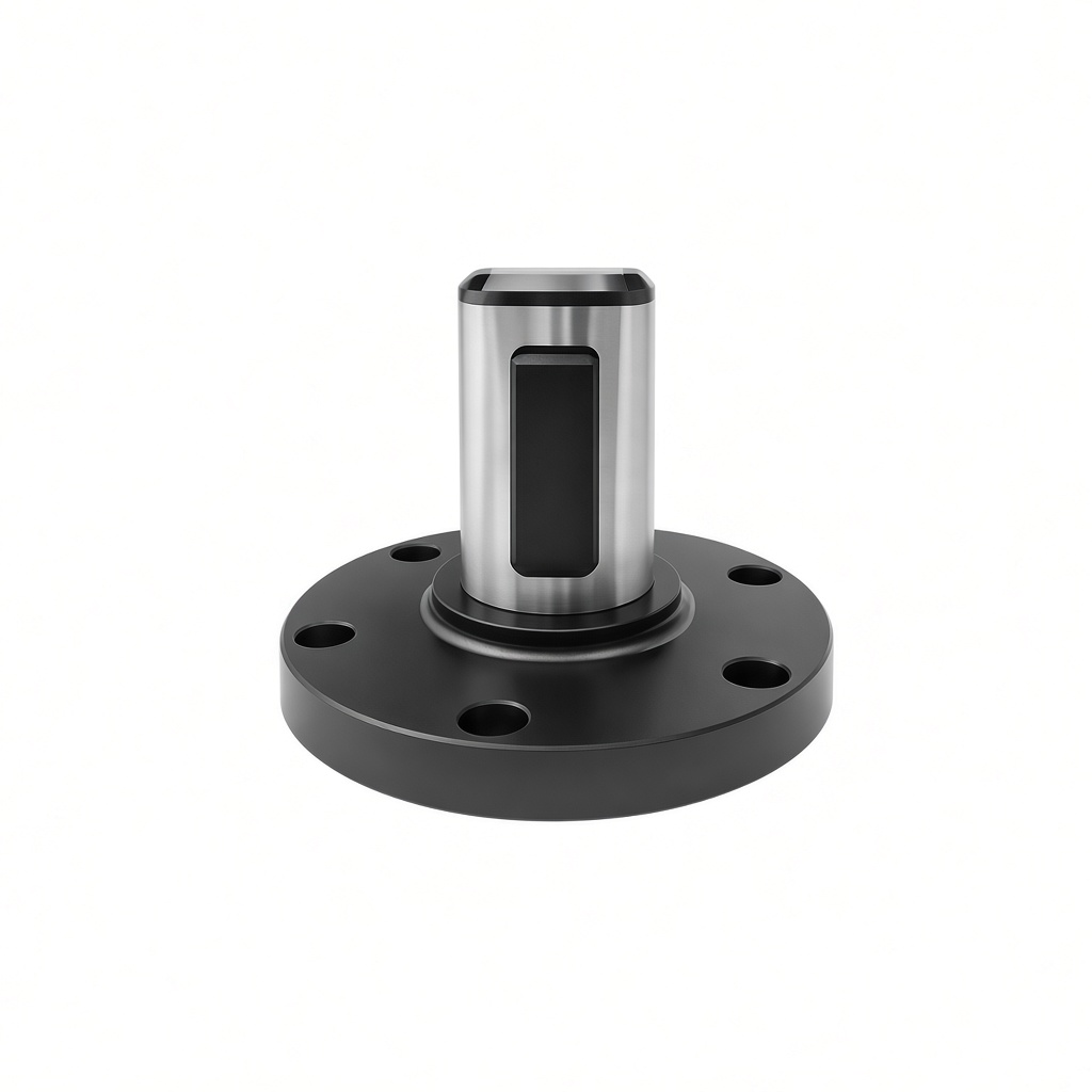
Support requirements can also shift between stages of machining. Roughing strips away a good chunk of material and changes the stiffness of whatever's left behind, while finishing usually calls for a setup that's dialed in more carefully. Matching the workholding to each stage as it comes helps keep the part behaving consistently throughout.
Why Does Deformation Sometimes Show Up After Machining?
A workpiece can look perfectly stable while it's clamped, then change shape the moment the holding force lets go. That happens because the part temporarily adapts to whatever pressure it's under during machining. Once released, it tends to drift back toward its natural, unstressed form.
Plenty of things feed into this. Uneven support, too much pressure, internal stress already baked into the material, thin sections, complicated geometry — any of these can shape how the part responds. Removing material during cutting shifts the internal balance of forces too, which adds another layer to the problem.
That's why inspection really needs to look at the workpiece across different stages — before clamping, during machining, and after release. Comparing those states helps pin down whether deformation actually traces back to the workholding setup. This kind of observation becomes especially useful once repeated production starts showing variation between otherwise identical parts.
How Do Expanding Core Chucks Support Hollow Components?
Expanding Core Chucks provide another option for holding hollow, cylindrical workpieces from the inside. They contact the inner surface while keeping much of the outer surface accessible for machining, which is useful when external features need to be processed without placing clamping pressure directly on those areas.
Whether this approach fits depends on the internal surface offering a decent spot for positioning and support. Rings, tubes, sleeves, and some housings tend to work well here, provided the internal geometry allows for secure contact.
Even so, internal expansion needs evaluating against the full machining process, not on its own. The workpiece has to stay properly located as cutting forces shift, and the support arrangement needs to keep making sense as material gets removed along the way. A method that suits one geometry perfectly well might need real adjustment for another.
What Factors Shape Clamping Pressure Control?
Controlling pressure matters a lot when machining thin walls, and it's not just about wall thickness on its own. Contact area, surface condition, geometry, machining forces, and any supplementary support all feed into how the part actually responds.
It helps to look at the whole setup rather than just cranking clamping pressure up or down in isolation. A workpiece with support spread well across its surface can hold steady under controlled pressure, while another part with limited contact might behave completely differently under seemingly similar conditions.
Watching results at each machining stage helps too. Changes in roundness, dimensions, surface finish, vibration, or positioning often signal that the workholding setup needs a second look. Thinking about the process this way ties observed outcomes back to the actual conditions used during machining.
How Does Workholding Influence Batch Production?
Thin-walled components generally need consistent handling once they're being produced over and over. A setup that works fine for one part should give roughly the same positioning and support to the next one in line. Otherwise, small differences in loading, contact surfaces, or clamping conditions creep in and cause variation nobody wants.
Regular checks on the chuck and its contact surfaces help keep conditions steady. Clean contact areas, stable positioning, repeatable loading methods — all of it adds up to a process that's easier to predict. Comparing parts before and after release can also flag changes that trace back to workholding specifically.
The real goal is a repeatable setup, not one built on brute force. Consider the workpiece, the support method, and the machining sequence all together, and the holding process becomes something you can actually manage across repeated runs.
What Should Manufacturers Weigh When Choosing a Workholding Method?
Picking a workholding method should start with the workpiece itself, not the chuck in isolation. Wall thickness, inner and outer geometry, how much machining access is needed, cutting direction, support requirements, and the realities of production all factor into that decision.
External gripping suits some shapes just fine, while internal expansion works better for hollow parts. Longer or more flexible sections might need supplementary support layered on top. Some jobs even call for combining locating and supporting methods to get a setup that actually holds up.
Manufacturers also need to consider how the workpiece changes as machining progresses. Material removal can alter stiffness and force distribution within the part, so the setup needs to remain suitable throughout the process rather than only when the workpiece is initially loaded.
How Can Chucks Support Stable Thin-Walled Machining?
Handling thin-walled workpieces comes down to a balance — secure positioning on one side, controlled force on the other. Mechanical Chucks offer solid external holding for a lot of applications, while an Expanding Mandrel Chuck or Expanding Core Chucks bring internal support into play for hollow components that suit the approach.
What really matters is how the workholding system interacts with the workpiece as a whole. Clamping pressure, contact area, support position, machining forces, material behavior — all of these feed into the final result together. Weigh them together, and manufacturers can cut down on unwanted deformation while keeping the machining process stable.
Thin-walled machining, in the end, isn't purely a cutting problem. It's a workholding problem just as much. A setup that's actually been thought through keeps the part properly positioned throughout production, while still letting the machining process respond to the real geometry and behavior sitting in front of it.
