


Ruian Chuangbo Machinery Co., Ltd. is specialized in manufacturing of machinery parts.
Tension variation in a slitting line does not always announce itself dramatically. Sometimes it shows up as a finished roll that is tighter on one side than the other. Sometimes it is a recurring edge curl that the operator keeps adjusting for without ever eliminating the root cause. Other times it is material slip during high-speed winding that introduces a slight shift in each successive layer, producing a roll that looks acceptable until it reaches the converting press and causes registration errors. These problems share a common origin: the interface between the core and the shaft is not providing a consistent, uniform grip across the full width of the roll. Pneumatic Air Shaft technology addresses this interface directly — not by adding more mechanical force, but by distributing the gripping mechanism in a way that mechanical chucks and friction-fit mandrels fundamentally cannot replicate.
What Causes Uneven Tension in a Slitting Line?
The Mechanical Origins of Web Handling Instability
Understanding why tension variation occurs is a prerequisite for understanding why the shaft design matters. Slitting lines move web material — film, paper, foil, nonwoven — through a series of driven and passive rollers at speed. Tension is the controlled resistance against which the material is pulled. Too little tension and the web sags, wanders, or telescopes on the rewind roll. Too much and the material stretches, the edges distort, or the core deforms.
A problem with mechanical shaft systems is that the gripping force they apply to the core is not uniform across the core's inner surface. A friction plug or a mechanical expansion key applies force at discrete points or along a limited contact line. Under dynamic conditions — speed changes, web variations, roll weight accumulation — those discrete contact points allow micro-movement between the core and the shaft. That micro-movement is the source of much tension variation that cannot be resolved by adjusting brake or drive settings.
Contributing factors that amplify this core-shaft instability:
- Core bore diameter variation between batches, even within specification
- Core surface finish variation that affects friction at contact points
- Temperature-induced dimensional change in the shaft body during extended runs
- Asymmetric web loading when slitting multiple widths of different thickness
Each of these variables interacts with how the shaft holds the core — and a shaft design that relies on concentrated contact points has no mechanism to compensate for them dynamically.
How a Pneumatic Air Shaft Creates Uniform Core Grip
The Inflation Mechanism and What It Actually Does
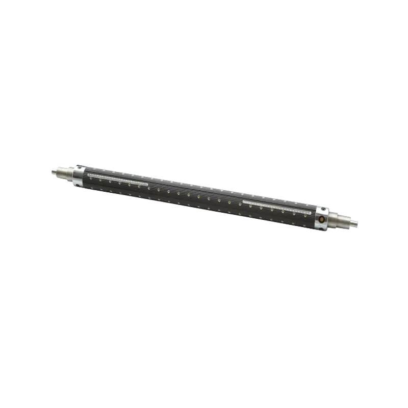
A Pneumatic Air Shaft holds cores through radial expansion driven by compressed air. The shaft body contains one or more bladder elements — flexible tubes that run along the shaft's length. When air pressure is applied through the shaft's internal valve, the bladder inflates outward, pressing against the inner surface of the core along its full circumference and full length simultaneously.
The contact is not at discrete points. It is a continuous, circumferential grip across the entire core bore surface. When the bladder inflates to the operating pressure, every section of the core bore is in contact with the expanded bladder at the same pressure. The gripping force is distributed — not concentrated — and that distribution is what produces the tension stability that mechanical systems struggle to replicate.
What this means in practice:
- Core bore variation is accommodated by the bladder, which conforms to the actual bore diameter rather than requiring precise matching
- Micro-movement between the core and the shaft is eliminated because there are no discrete contact points to slip
- Torque transmission is spread across the full core contact area, reducing stress concentration at the core ends
- Loading and unloading is done by releasing the air pressure, which deflates the bladder and releases the core without tool use or manual adjustment
The consistency of this grip across operating conditions — at speed, under load, through speed changes — is the mechanism by which uneven tension problems are addressed.
Why Does a Multi Bladder Air Shaft Outperform Single Bladder Designs?
Force Distribution Across Width and Its Effect on Roll Quality
A single bladder running the full shaft length provides substantially better core grip than a mechanical system. But it has a limitation: if the bladder inflates unevenly along its length — due to internal pressure variation, local wear, or differential expansion — the gripping force can still vary from one end of the core to the other.
A Multi Bladder Air Shaft addresses this by dividing the inflation mechanism into multiple independent bladder segments distributed along the shaft. Each segment inflates to operating pressure, and the multiple contact zones together produce a more uniform gripping force profile across the full core width than a single continuous bladder can achieve.
This matters particularly in applications where:
- Wide cores are used and shaft deflection under load changes the contact geometry along the length
- High-speed operation creates dynamic imbalance that a single bladder cannot fully compensate for
- Different core widths are used on the same shaft, requiring consistent grip regardless of where the core sits along the shaft length
- Heavy rolls accumulate significant mass during winding, increasing the differential between center and end loading
For slitting lines running wide formats or high-speed rewind cycles, the multi bladder configuration reduces the tension variation that even a well-maintained single bladder system may introduce.
What Are Air Shaft Parts and How Do They Affect Performance?
The Component-Level Understanding Behind Maintenance Decisions
A Pneumatic Air Shaft is not a monolithic component — it is an assembly of parts, each with its own service life and failure mode. Understanding these parts helps operators identify when performance degradation is happening and what is causing it.
Shaft body: The structural core of the assembly, typically machined from steel or aluminum alloy. The body contains the air distribution channels that carry compressed air from the valve fitting to the bladder elements. Shaft body condition affects both mechanical rigidity and air distribution uniformity.
Bladder elements (Air Shaft Bladder Tubing): The expandable tubes that provide the radial gripping force. Bladder tubing is the highest-wear element in the shaft assembly. It is subject to repeated inflation and deflation cycles, friction from core bore contact, and chemical exposure from any coatings or release agents used on cores. Bladder degradation — cracking, loss of elasticity, pinhole leaks — is a common source of grip inconsistency in a shaft that had been performing well.
Valve fitting: The connection point through which compressed air enters the shaft. Valve condition affects how quickly the bladder inflates and whether pressure is maintained consistently during operation. A worn or partially blocked valve produces slower inflation and lower operating pressure, both of which reduce gripping force.
End flanges and bearing journals: These structural elements locate the shaft in the machine's bearing housings and transmit the drive or brake torque from the machine to the shaft. Wear or damage at these points introduces runout — radial wobble — that affects winding geometry and adds dynamic tension variation.
Bladder retaining components: Clips, end caps, or channel features that keep the bladder in position against the shaft body during inflation. If these allow the bladder to migrate or balloon unevenly, the grip force distribution changes in ways that introduce exactly the tension variation the shaft is meant to prevent.
How Air Shaft Bladder Tubing Wear Affects Tension Stability
Recognizing Degradation Before It Becomes a Quality Problem
Air Shaft Bladder Tubing operates under conditions that inevitably cause wear. The key is recognizing the progression of degradation before it produces visible quality problems in the finished roll.
Early-stage bladder wear signs:
- Slightly longer inflation time to reach operating pressure (air loss through micro-porosity in the bladder wall)
- Occasional core release difficulty after deflation (bladder surface has lost its release characteristics)
- Very minor variation in roll hardness from one end to the other (uneven bladder contact beginning to develop)
Progressed wear signs:
- Audible air leakage during operation (bladder breach or fitting seal failure)
- Inconsistent core grip — cores that held firmly previously now slip under the same operating pressure
- Roll telescoping or edge wander that cannot be corrected by tension system adjustment
- Visible cracking or surface degradation on the bladder tubing surface during routine inspection
At progressed wear stage, the bladder should be replaced before a production run rather than during one. Running a slitting line with degraded bladder tubing produces yield losses — scrap rolls, rework, material waste — that far exceed the cost of a bladder replacement performed proactively.
Comparing Air Shaft Types for Slitting Applications
Different shaft configurations suit different slitting line requirements. The comparison below reflects typical operational differences:
| Shaft Type | Grip Mechanism | Core Width Suitability | Speed Range | Tension Uniformity | Typical Application |
|---|---|---|---|---|---|
| Single Bladder Pneumatic | Full-length inflation | Narrow to moderate | Moderate to high | Good | General film and paper slitting |
| Multi Bladder Pneumatic | Segmented inflation zones | Wide to very wide | High | Very good | Wide-format, high-speed slitting |
| Mechanical Expansion (Key Type) | Discrete key contact | Narrow to moderate | Moderate | Variable | Lower-speed, lower-precision applications |
| Friction Plug / Chuck | Point contact at ends | Any width | Lower | Poor at speed | Manual or semi-automatic winding |
The pattern is consistent with what the mechanism analysis predicts: pneumatic shaft configurations produce more uniform tension than mechanical alternatives, and multi bladder configurations extend that uniformity to wider formats and higher operating speeds.
Unwind vs. Rewind: Do Tension Demands Differ?
Why the Same Shaft May Need Different Configuration at Each Station
Slitting lines have distinct tension demands at the unwind and rewind stations, and these differences affect how the shaft at each position should be configured.
At the unwind station, the shaft holds a full parent roll that decreases in diameter and mass as the material feeds into the line. The tension demand on the unwind shaft is primarily braking — resisting the pull of the web drive while maintaining consistent back-tension. As the roll reduces in diameter, the braking torque required to maintain the same web tension changes, which is why unwind stations use brake systems rather than drives.
At the rewind station, the shaft supports a growing roll and must transmit drive torque from the machine into the core consistently as the roll builds in mass and diameter. The gripping requirement here is about torque transmission, and grip failure at the rewind results in core spin — the roll loses the drive and the core turns while the outer layers stop, creating a catastrophic slippage event.
Both stations benefit from pneumatic shaft technology, but the failure mode of poor grip is different:
- At the unwind: poor grip allows the core to rotate relative to the shaft during braking, producing tension spikes
- At the rewind: poor grip allows core spin, which destroys the roll and potentially damages the shaft
Multi bladder configurations are particularly valuable at the rewind station on wide-format lines, where the mass of a full roll creates significant differential loading across the shaft length.
Integrating Air Shaft Performance Into the Broader Tension Control System
Why the Shaft Is One Element of a System
A pneumatic shaft solves the core-to-shaft interface problem. It does not replace the broader tension control system — the brake and clutch mechanisms at the unwind, the drive control at the rewind, the dancer roll or load cell feedback that provides tension measurement. All of these elements work together, and improving the shaft's grip consistency makes the rest of the tension control system more effective by removing a source of variation that it previously had to compensate for.
When a slitting line has good pneumatic shaft grip across both stations, the tension control loop operates with less noise — the feedback signal from the web reflects actual web tension rather than a combination of actual tension plus core-slip artifacts. The result is tighter tension regulation, more consistent roll quality, and less time spent on manual adjustment between roll changes.
This system-level perspective is why upgrading to pneumatic shaft technology often produces quality improvements that go beyond what the shaft alone would suggest. The shaft improvement enables the tension control system to perform at a higher level.
Selecting the Right Air Shaft Configuration for Your Line
Before specifying a pneumatic shaft, several application parameters need to be defined:
- Core bore diameter range — the bladder must expand into the smallest bore and contract fully below the largest bore in the range
- Core width range — determines shaft working length and whether multi bladder configuration is required
- Operating speed — higher speeds require more precise balance and potentially more robust bladder construction
- Torque requirement — the torque at the shaft determines the needed gripping force at operating pressure and influences bladder design.
- Material being processed — some materials require careful management of core pressure to avoid core deformation under the gripping force
These parameters, provided accurately to a shaft supplier, produce a specification that suits the actual application rather than a generic catalog selection that may underperform at the operating edges.
Working With a Supplier Who Understands Web Handling Engineering
Air shaft performance depends on design quality, material selection for the bladder elements, and manufacturing precision in the shaft body and bearing journals. A shaft that meets general specifications but is manufactured with insufficient precision in the bladder channels or the valve system will produce exactly the kind of inconsistent grip that the technology is meant to eliminate. Ruian Chuangbo Machinery Co., Ltd. manufactures Pneumatic Air Shafts and related web handling components for slitting, rewinding, and converting applications, with product range covering single and multi bladder configurations, replacement Air Shaft Parts, and Air Shaft Bladder tubing suited to a variety of core bore sizes and operating conditions. Their engineering team can work through application parameters to specify the shaft configuration that addresses the tension control requirements of a specific slitting line. If you are experiencing uneven tension or roll quality issues in your slitting operation, or if you are specifying shafts for a new line, reaching out to discuss the application in detail is a practical way to identify whether the shaft configuration is the right place to start the improvement.
