


Ruian Chuangbo Machinery Co., Ltd. is specialized in manufacturing of machinery parts.
Tension problems on a web line often do not come from faulty components — they come from components that are correctly built but placed in the wrong position within the system. If a winding line is struggling to hold consistent tension, or if torque is transmitting unevenly through a drive chain, the question is not just whether the device is performing to specification.It is whether the right type of device was selected for that position initially. Both a Magnetic Powder Brake Manufacturer product and a magnetic powder clutch use the same underlying technology, but they serve opposing functions in a tension control architecture, and using one where the other belongs will produce instability that no amount of parameter adjustment can correct.
How Magnetic Powder Technology Works in Both Devices
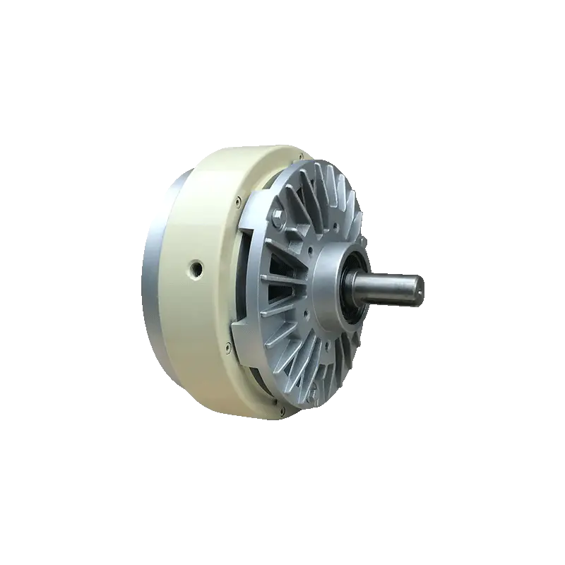
The Shared Operating Principle
Both the brake and the clutch use magnetizable powder — fine iron particles — as the torque-transmitting medium. When electrical current flows through the coil, it generates a magnetic field that causes the powder particles to form chains aligned with the field. These chains create friction and binding force between the rotating input and the adjacent surface, transmitting torque proportionally to the applied current.
Reducing current breaks down the powder chains and reduces torque. The relationship between current and torque is smooth and controllable, which is why both devices are used in tension control applications where graduated, adjustable force is required.
Where the Designs Diverge
Despite the shared operating principle, the two devices are structurally different — and that structural difference defines their functional roles.
In a Magnetic Powder Brake, one side of the device is fixed. The rotating input is the shaft connected to the unwinding roll or the moving web; the opposing surface is stationary. The powder transmits force between motion and stillness, creating resistance rather than driving motion. The output is a braking torque — a force that opposes rotation.
In a magnetic powder clutch, both sides are capable of rotation. The input connects to a drive source; the output connects to the driven component. The powder transmits torque from the driving side to the driven side, allowing controlled power transfer between two rotating shafts.
Same powder. Same electromagnetic principle. One creates resistance. One transmits drive. The position in the system determines which is needed.
What Does a Magnetic Powder Brake Do in a Tension System?
A Magnetic Powder Brake applies a controlled retarding force to a rotating shaft. In web processing equipment, this is the device that holds an unwinding roll back — creating the back-tension that keeps the web taut as it feeds into the process.
Without this retarding force, the unwinding roll would spin freely, the web would go slack, and the process downstream would lose the tension control it depends on for registration accuracy, consistent coating weight, or clean slitting. The brake creates the controlled resistance that makes the unwinding side of the system behave predictably.
Key functional characteristics in this role:
- Current to the brake coil is adjusted in real time based on tension feedback — increasing current increases braking force, which increases web tension
- As the roll diameter decreases during unwinding, the geometry of the system changes; the brake current is adjusted to compensate and maintain consistent web tension
- The brake absorbs the rotational energy of the unwinding roll and converts it to heat — which is why thermal management is a design consideration for continuous-duty brake applications
What Does a Magnetic Powder Clutch Do in a Tension System?
A magnetic powder clutch sits on the drive side of the system. It controls how much torque is transmitted from a drive motor or shaft to the component being driven — a winding reel, a nip roll, a feed roll, or another driven element.
In a winding application, the clutch controls how much drive torque reaches the winding reel. As the wound roll grows in diameter, the torque required to maintain constant web tension changes; the clutch adjusts the transmitted torque to compensate, keeping tension steady as the winding geometry evolves.
Key functional characteristics in this role:
- The drive motor runs continuously; the clutch modulates how much of that drive reaches the output shaft
- In a slipping clutch configuration, the input and output can run at slightly different speeds, allowing the system to absorb minor speed variations without tension spikes
- Torque is proportional to current — the same control approach as the brake, applied to power transmission rather than resistance
The Core Distinction: Resistance vs. Transmission
This is the functional boundary that determines which device belongs where:
- A Magnetic Powder Brake creates resistance. It opposes motion. It belongs where the system needs to slow down or hold back a rotating element.
- A magnetic powder clutch transmits power. It passes motion forward. It belongs where the system needs to drive a rotating element with controlled torque.
Placing a brake where a clutch is needed means there is no drive force where the system expects one. Placing a clutch where a brake is needed means the system loses its retarding force and cannot hold back tension on the supply side.
These are not interchangeable errors. Each produces a specific and recognizable failure pattern in the tension system — but both are avoidable by correctly mapping the device function to the system position during design.
Side-by-Side Comparison
| Factor | Magnetic Powder Brake | Magnetic Powder Clutch |
|---|---|---|
| Primary function | Creates resistance — opposes rotation | Transmits torque — drives rotation |
| Output side condition | Fixed or stationary | Rotating — connected to driven load |
| System position | Unwinding / supply side | Winding / drive side |
| Tension control role | Holds back web tension | Applies winding tension |
| Response to current increase | Increases braking force | Increases transmitted torque |
| Heat generation source | Slip between rotating input and fixed housing | Slip between input and output shafts |
| Typical application context | Unwinding rolls, feed tension control | Winding rolls, driven feed systems |
| Cooling requirement | Higher in continuous-duty unwinding | Moderate — depends on duty cycle and slip |
Where Each Device Belongs in a Web Processing Line
Unwinding Section
The unwinding reel holds the raw material roll. As the web is pulled into the process, the unwinding reel must be controlled to prevent it from overrunning and creating slack. A Magnetic Powder Brake on the unwinding shaft provides the controlled resistance that keeps the web taut.
A clutch at this position would not serve this function — it transmits torque rather than opposing it, and the unwinding section needs opposition, not drive.
Drive Section
Nip rolls, pull rolls, and feed rolls in the middle of the process are typically driven directly by motors and do not require either device. Tension at these points is controlled by speed relationship between rolls rather than by individual torque devices.
Winding Section
The winding reel must take up the processed web at a controlled rate. As the wound diameter grows, the torque required to maintain consistent tension increases. A magnetic powder clutch on the winding reel shaft allows the drive motor to transmit controlled, adjustable torque to the reel, compensating for the changing geometry.
A brake at this position would prevent the reel from winding correctly — it would oppose the driving force rather than transmitting it.
Can the Same Device Serve Both Roles?
No — not without significant redesign. The structural difference between the two (one side fixed vs. both sides rotating) is fundamental to how the device functions. A Magnetic Powder Brake cannot be reconfigured as a clutch, and vice versa, through parameter adjustment alone.
In some systems, both devices are used simultaneously:
- A brake on the unwinding shaft controls supply-side tension
- A clutch on the winding shaft controls take-up tension
- Together, they create a closed-loop tension architecture across the full width of the process
This combined approach is common in higher-precision applications — printing presses, multi-layer lamination lines, slitting operations — where both supply and take-up tension must be independently controlled to maintain web stability throughout the process.
How Does Torque Control Differ Between the Two?
Control Input and Response
Both devices respond to electrical current in a proportional and smooth way. Increasing current increases force — braking force in the brake, transmitted torque in the clutch. Decreasing current reduces force. This shared characteristic makes both devices compatible with closed-loop control systems that use tension sensors or dancer roll feedback.
The difference is in what that force does to the system. In the brake, more force means more resistance — the web gets tighter on the supply side. In the clutch, more force means more drive — the winding reel turns harder and takes up more web per rotation, which also tightens the web but from the take-up side.
Both ends of the tension system can therefore be independently adjusted by separate devices, which is the basis of stable closed-loop tension control in demanding applications.
Hysteresis and Response Speed
Both devices exhibit some hysteresis — a small difference between the rising and falling torque response at the same current level. This is inherent to magnetic powder technology and is a manageable characteristic in well-tuned control systems. The degree of hysteresis is not identical between a brake and a clutch of the same nominal rating, because the mechanical configuration and the way the powder loads are different. Control system tuning should account for the specific hysteresis characteristics of each device in the loop.
Common Selection Mistakes and Their Consequences
Specifying a Brake for a Winding Application
A brake on the winding reel will oppose the winding drive, reducing or reversing the effective torque at the reel. The result is inconsistent or insufficient take-up tension, web sag between the process and the winding reel, and potential web breaks or misalignment at higher speeds.
Specifying a Clutch for an Unwinding Application
A clutch cannot provide the fixed resistance that unwinding tension control requires unless connected to a stationary load — which defeats the purpose of the device. Attempting to use a clutch on the supply side typically results in insufficient or uncontrolled back-tension, slack in the web, and loss of registration or process consistency downstream.
Under-Specifying Thermal Capacity
Both devices generate heat through slip. In continuous-duty applications, the thermal capacity of the device must match the duty cycle. A correctly typed device that is thermally under-specified will still fail — not through incorrect placement, but through overheating under sustained operation. Cooling method and rated duty cycle should be part of the selection specification alongside torque rating and shaft dimensions.
The selection decision between a magnetic powder clutch and a Magnetic Powder Brake is not a preference question — it is a system architecture question. The answer comes from the position in the line, the direction of force required, and the tension control objective at that stage of the process. Getting this right at the design stage prevents tension instability, reduces mechanical stress on the web and the equipment, and simplifies the control system tuning that follows. Ruian Chuangbo Machinery Co., Ltd. manufactures Magnetic Powder Brakes and clutches for web tension control applications in printing, packaging, slitting, and converting lines, with engineering support covering system configuration, device sizing, and control integration. If you are designing a new tension control system or troubleshooting instability in an existing line, reaching out to their technical team is a practical way to confirm whether the current device placement and specification matches the system's actual operating requirements.
