


Ruian Chuangbo Machinery Co., Ltd. is specialized in manufacturing of machinery parts.
Roll handling is one of those production variables that looks straightforward on paper and reveals its complexity during sustained operation. In a printing environment where material runs continuously through tension-controlled systems, the speed and reliability of roll changes directly determines how much of a shift is spent producing rather than waiting. A poorly designed or worn roll-locking mechanism adds minutes to every changeover, and those minutes accumulate into hours across a week of production. Pneumatic Air Shafts address this problem at the mechanical level — by replacing friction-dependent or manual-tightening systems with air-actuated expansion that locks the core consistently, every time, without operator variability.
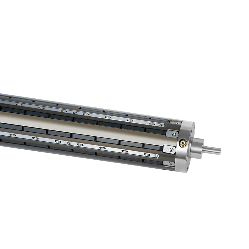
What Is a Pneumatic Air Shaft?
A Pneumatic Air Shaft is a cylindrical shaft fitted with an internal bladder or a series of expansion elements that inflate when air pressure is applied. When deflated, the shaft slides freely into a paper, film, or foil roll core. When pressurized, the expansion elements extend outward to grip the inner surface of the core, locking the roll to the shaft for winding or unwinding. Releasing the pressure collapses the elements and allows the core to slide off without tools or manual adjustment.
The mechanism replaces older approaches — taper-lock systems, set-screw arrangements, or friction sleeves — that required physical manipulation at each roll change and introduced dimensional variability depending on how tightly the operator applied the locking mechanism. The air-actuated version removes that variability by applying a consistent radial gripping force determined by the inflation pressure rather than by hand torque.
Why Printing Operations Depend on This System
Roll Changeover Speed Drives Productivity
In commercial printing, packaging, and label production, rolls of substrate must be replaced every time a parent roll is exhausted. The time between the end of one roll and the start of the next — loaded, locked, tensioned, and running at speed — represents unproductive machine time. With a pneumatic system, that sequence is reduced to: deflate, remove core, slide on new core, inflate, resume. The entire operation can be completed in under a minute by a single operator, compared to several minutes for manual systems that require tools or multiple adjustment steps.
Across a production day with multiple roll changes, the cumulative difference is significant. A printing line running multiple substrate widths or frequent job changes benefits proportionally more, since the changeover count is higher.
Tension Stability Across the Roll Diameter
As a roll unwinds and its diameter decreases, the rotational inertia of the system changes. A shaft that grips inconsistently — tighter at some points, looser at others due to core diameter variation or manual tightening differences — introduces tension fluctuation that manifests as register error, color variation, or substrate wrinkling in the printed output. The uniform radial grip of a pneumatic shaft maintains consistent coupling between the shaft and the core across the full roll diameter range, which supports stable web tension from the full roll through to the core.
This consistency is particularly relevant in flexographic and gravure printing, where register tolerances are tight and any tension disturbance in the unwind or rewind station propagates through the web path.
Handling Across Core Size Variations
Roll cores are not produced to perfectly uniform internal diameters. The tolerance range across a production batch of cores — even from the same supplier — means that a fixed-dimension shaft would grip some cores tightly and others loosely. A pneumatic shaft compensates for that variation automatically: the bladder or expansion elements fill the available gap regardless of whether the core is at the narrow or wide end of its tolerance band. This adaptability eliminates the sorting, shimming, or rework that some manual systems require when core dimensions vary.
Leaf Type vs. Lug Type: How the Expansion Mechanism Differs
The internal expansion mechanism is what distinguishes the main structural categories of pneumatic shafts, and that distinction affects grip pattern, load capacity, and suitability for different applications.
| Feature | Leaf Type Air Shaft | Lug Type Air Shaft |
|---|---|---|
| Expansion Element | Continuous metal leaves along the shaft length | Individual lugs or keys that project radially |
| Grip Pattern | Distributed along the full contact length | Concentrated at lug positions |
| Suitable Load | Heavier rolls, wider webs | Standard-weight rolls, general printing |
| Core Contact | High-contact, even surface grip | Point or line contact at lug intervals |
| Maintenance | Leaf replacement when worn | Individual lug replacement |
| Typical Application | Wide-format printing, heavy film rolls | Label printing, narrow web, packaging |
A Leaf Type Air Shaft uses spring-steel or hardened leaves that run along the shaft's length and expand outward uniformly when the bladder inflates. The result is a high-contact grip distributed across the full interior surface of the core, which makes this construction suitable for heavier rolls where concentrated contact would risk damaging the core or producing uneven gripping force.
A Lug Type Air Shaft uses discrete projecting elements — lugs or keys — that extend radially at defined intervals around the shaft circumference. When inflated, the lugs engage the core interior at those points. This construction is easier to maintain because individual lugs can be replaced without removing the entire expansion system, and the simpler internal geometry is more tolerant of contamination from ink, dust, or adhesive residue common in printing environments.
Multi Bladder Air Shaft Construction and Its Advantages
A multi bladder air shaft uses more than one independent bladder chamber within the shaft body, each controllable separately or inflated from the same air supply. The design distributes inflation force more evenly along the shaft length than a single-bladder construction, which is relevant for wide or heavy rolls where a single bladder might allow the shaft to bow slightly under load — particularly at the center span between bearing supports.
The pressure distribution advantage of a multi-bladder system also reduces the risk of core distortion. A single high-pressure bladder concentrates its expansion force at the bladder's contact zone; a multi-bladder system spreads that force more evenly, which protects cores made from softer materials — recycled paperboard, thin-wall plastic — that can deform under localized high-contact pressure.
For printing operations running wide web widths or heavy parent rolls, specifying a multi-bladder construction is worth evaluating against the simpler single-bladder alternative, particularly when core damage or center-span deflection has been a recurring issue.
The Role of Lightweight Air Shafts in Modern Printing Lines
Not all printing applications involve heavy rolls. Label printing, narrow-web flexo, and short-run digital finishing operations work with rolls that are light enough to handle manually but still benefit from the consistent core grip and fast changeover that pneumatic expansion provides.
In these applications, a lightweight air shaft — built from aluminium alloy rather than steel, or with a reduced wall section — offers the same gripping mechanism at a fraction of the weight of a standard shaft. The reduced shaft weight matters in two ways: it lowers the physical demand on operators who handle shafts repeatedly throughout a shift, and it reduces the rotational inertia of the shaft-and-core system, which improves the responsiveness of tension control systems during acceleration and deceleration.
Bladder Material, Tubing, and Why They Determine Service Life
In a pneumatic shaft, the bladder fails prior to other components, and its material composition affects the service duration before replacement is required. Air shaft bladder material is typically natural rubber, silicone, or a synthetic elastomer formulation, each with different resistance profiles for temperature, chemical exposure, and pressure cycling fatigue.
In printing environments where solvent-based inks or UV-curable coatings are in use, the bladder material must resist chemical attack from solvent vapor that enters the shaft body through the core interface. A bladder material that degrades under solvent exposure will crack, lose pressure retention, and eventually fail to maintain grip — often without visible external indication until the shaft slips under load.
Air shaft bladder tubing connects the bladder to the inflation valve and must maintain pressure integrity through repeated inflation and deflation cycles over the shaft's service life. Tubing failure — cracking at the valve fitting, pinhole development from flex fatigue — typically manifests as slow pressure loss that the operator notices as a gradual reduction in core grip rather than an immediate system failure. Inspecting the tubing at scheduled maintenance intervals prevents in-production failures that are more disruptive than planned replacements.
Air Shaft Spare Parts and Maintenance Intervals
A pneumatic shaft in continuous production use requires periodic replacement of its wear components. The components that commonly need attention are:
- Bladders and tubing: Subject to pressure cycling fatigue and chemical exposure; replacement interval depends on operating hours and environmental conditions
- Leaf or lug elements: The gripping surfaces that contact the core interior; wear rate depends on core material hardness and how frequently the shaft is inserted and removed
- Inflation valves: The Schrader or custom valves through which air is introduced; seal degradation causes slow pressure loss
- End caps and bearing seats: Subject to wear from the shaft support bearings; dimensional wear affects shaft alignment in the machine
Maintaining a stock of air shaft spare parts for the shaft types in operation prevents extended downtime when a component fails during production. For non-standard spare parts sourced from a distant supplier, the delivery period can be long; having critical components on hand turns an unplanned failure into a planned maintenance event.
A structured maintenance schedule — bladder inspection at defined hour intervals, leaf or lug wear check during scheduled downtime, valve seal replacement at predetermined cycles — extends the service life of the shaft body, which represents the larger part of the total asset value.
Sourcing Pneumatic Air Shafts and Components
For printing operations sourcing replacement shafts or spare components, the decision between a domestic distributor and a direct factory relationship affects both unit cost and the availability of non-standard specifications. Custom shaft lengths, non-standard core diameters, specific bladder materials, or multi-bladder configurations are more readily available from a manufacturer with OEM capability than from a distributor carrying a fixed catalogue range.
China air shaft manufacturers have developed significant production depth in this product category, supplying both standard and custom shaft specifications to printing operations across Asia, Europe, and North America. Factory-direct sourcing allows for custom specifications and volume pricing, but the initial order process entails longer delivery times and the need for clear technical communication during specification. Ruian Chuangbo Machinery Co., Ltd. manufactures Pneumatic Air Shafts across leaf type, lug type, and multi-bladder configurations, with production capability for custom lengths, core diameter ranges, and bladder material specifications suited to specific printing and converting environments. For procurement teams evaluating shaft specifications or sourcing spare components for existing shafts, contacting the manufacturing team with dimensional requirements and operating conditions is the starting point for identifying the appropriate product configuration.
